“If you can make a dipole antenna, then you can make any antenna.” – NC Scout
Background
The Jungle or Quarterwave Groundplane Antenna is an omni-directional antenna that was designed to be field-expedient and to enhance radio communications in the dense jungle.
If you understand the theory, then you can build any kind of antenna from these principles.
Dipole Antennas
Wavelength – the distance a radio wave will repeat its cycle. Our example here is MURS 3 (151.940 MHz) which has a wavelength (λ) of 6.36 feet. This frequency is in the 2-meter band (1.97 meters). Note that you cannot transmit on this frequency unless you have a Part 95 MURS radio or have a true emergency.
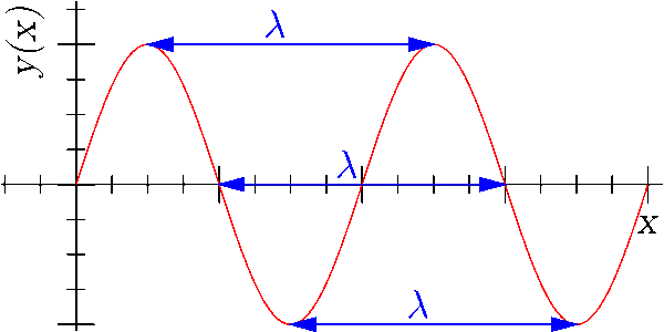
Dipole Antennas made for a frequency should measure 1/2 of a Wavelength (typically seen as λ/2).
This length is where the antenna needs to be resonant (“tuned”) on the frequency you want. Best practice is to transmit on the most resonant antenna available. If you use an antenna that is not resonant, then it won’t transmit as well and a portion of that radio energy turns to heat.
Since there are two legs (di-pole), each leg is 1/4 of a wavelength (λ/4). We can easily remember the formula using the mnemonic 1234. Find the length of each leg by using the formula:
1 leg (in feet) = 234 / frequency (in megahertz)
There are other considerations (wire material, wire gauge, coating, etc.) but this is a close estimate and good enough for a field expedient antenna.
Ground Plane
Some antennas are designed to work with a ground plane. An example is a magnetic-mount CB antenna on a car roof. It uses the metal roof as the ground plane for the antenna.
Some permanently mounted antennas will have small antenna stubs coming out of their base. These antennas will use three or more radials to create a virtual ground plane.
Our jungle antenna will use one upright as the radiator and three radials (“legs”).
Supplies (Jungle Antenna Kit)
- One Split post BNC adapter (AKA “Cobra Head”)
- Four Ring terminals that fit on the BNC adapter posts. A bit larger is ok.
- A length of wire about 10’ – Can be 20 AWG primary wire, 14-gauge THHN, or even lamp cord.
You will also need to obtain
- Four insulators (e.g. zip ties, bootlaces, electric fence insulators, cut PVC pipe, etc.)
- A length of 550 cord for supporting the antenna over a tree branch
- Three straight sticks about 2.5 foot long and as big as your finger
Tools
- Measuring Tape
- Wire Snips
- Wire Strippers
- Wire Crimpers
Assembly
- Determine the frequency you want. In this example we will use MURS 3 (151.940 MHz).
- Find the leg length (in feet) equals (234/ frequency (MHz))
- Our formula is: 1 Leg = 234 / 151.940 MHz = 1.54 feet
- Convert to inches. (length in feet x 12) = length in inches
- This makes 1.54 feet x 12 = 18.48 inches (round to 18.5 inches)
- Add 3.5 inches for excess (.5 inch for the crimp and 3 inches for the insulation loop).
- So, 18.5 inches + 5.5 inches = 24.00 inches
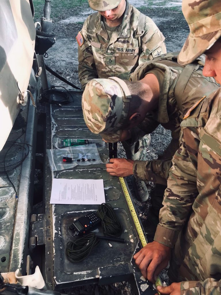
- Measure and cut your four lengths of wire.
- Measure and mark each wire 5 inches from the end. This is your excess to loop through the insulator or just make a loop and wrap the end twice around the wire at the mark.
- Strip a ½ inch off other end of each wire. Crimp on a ring terminal at this end.
- The distance between the crimp and the wrapped wire should be approximately close to the 18.5 inches (see #3 above). Close is good enough.
- Attach one antenna leg to the red-side (radiator/hot) of the Cobra Head.
- Attach one antenna leg to the black-side (ground/cold) of the Cobra Head.
Congratulations! You have created a dipole antenna that works better than the antenna that came with your handheld radio.
Now to improve it!
- Attach your other two legs to the black-side (ground/cold) of the Cobra Head.
- Find three straight sticks around 2 ½ feet long and finger sized. Place in shape of a triangle on the ground overlapping the ends.
- Cut three short lengths of 550 cord (15-20 inches long), or use cable-ties, twine, boot laces, etc.
- Hold the antenna above the triangle. Adjust the size of the triangle, to have the three black-side legs angled down at 45 degrees. Tie each of the black-side loops to the corners of the triangle.
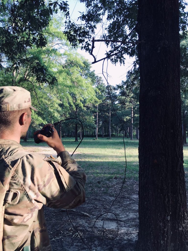
- Throw 550 cord over a tree branch and tie to the remaining red-side leg. (see picture above)
- Connect this antenna to your radio using a coax cable (max 20 feet with CB radio cable, or max 40 feet with RG-8X cable). The rule is: Use the shortest and best cable you can get.
- Hoist antenna into the air and tie off. Can hide antenna in branches, or keep clear of live tree trunks and branches for less interference and better distance.
To improve this antenna even more, adjust the three black-side legs and make them +12% longer. In our example, 20.7 inches instead of 18.5 inches between the crimp and wire wrap.
Performance
This Jungle Antenna increases your UHF/VHF performance in two ways: Antenna height and gain
- Antenna Height – UHF/VHF are line-of-sight frequencies, so if you hoist your antenna up into a tree it will increase your radio horizon. You will get even better range on a hill.
- Antenna Gain – Use this antenna over your handheld radio antenna to increase your antenna gain by 2 or 3 Db. Antenna gain is where your antenna is more focused to the horizon and is more sensitive. This means your average 5-watt radio could act more like a 10-watt radio and reach around 1.5 times further.
You can also increase performance from minimizing any inefficiencies.
- Longer cables introduce signal loss. Use a better antenna cable like LMR400 for longer runs. If you can’t use better cables, then severely limit the cable length when on VHF/UHF frequencies. As mentioned in the instructions, use a maximum of 20 feet for CB cable (RG-58), or 40 feet for RG-8X to limit the loss of signal power to the antenna.
- The kind and gauge of wire (and insulation) will affect the antenna. You can use barbed wire in a pinch, but use the best affordable wire available. If you have access to an antenna analyzer then you can measure the actual SWR of your antenna. You can then adjust the four leg lengths to have the lowest SWR (Standing Wave Ratio) on the frequency you wish to transmit or receive.
You can finally increase performance by increasing power.
- Increasing power does not increase your radio horizon, but it better pushes your signal through obstructions like trees or around buildings.
Mobile radios range from 20-100 watts output and run on 12v DC (actually 13.8v DC). The downside to running a mobile radio is that more power means larger and heavier batteries that are not as portable.
Application
This Jungle antenna can be created out of locally on-hand materials. It can be hoisted and hidden in the tree branches at a good transmitting location. Normally, this is a distance from your observation point (OP) or hide.
If you are on a long mission, then you can turn your radio power down and use communications windows to save your battery life.
Gallery

Cutting the wires 
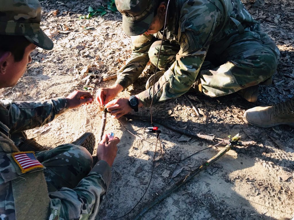
Attaching to the spreaders Using the jungle antenna
References/Sources
- https://brushbeater.wordpress.com/2015/10/15/the-jungle-antenna
- https://www.n6cc.com/antenna-system-ideas
- Military antenna diagram and other useful information from FM23-10 Chapter 7
- Other images from Wikipedia
Pingback: A Reader's CB Antenna Question - Paratus Radio
Pingback: Expedient Antennas: Commo for Family, Group, or Community - Survivalist Pros