“If you can make a dipole antenna, then you can make any antenna.” – NC Scout
Background
The Long Wire Directional Antenna is a field expedient antenna that was designed to transmit its signal in one direction. It is used by the military to setup at a covert transmitting location and is aimed towards their base. This is similar to a “Beverage Antenna” but with a higher watt resistor.
Directional means that more signal is pushed forward. There is less signal to the back and sides of the antenna. This reduces your transmitting radio signature which also reduces the chance an Opposing Force will either overhear your radio traffic or triangulate on your position and attack.
Description
We will be creating a VHF Long Wire Directional Antenna for our example of MURS 3 (151.940 MHz). Note that you cannot transmit on this frequency unless you have a Part 95 MURS radio or have a true emergency.
This antenna is an oversized dipole, where the radiating leg is 2+ times the half wavelength you are transmitting on. Instead of the legs in opposite directions like a normal dipole, the legs create a vertical loop of various shapes and touch each other.
At this contact point, a 10-watt, 450-600 Ohm resistor (or a dead AA battery) is placed that can handle the power output of our handheld radio. This resistor prevents the radio signal traveling backwards on the leg, causing the radio wave only to move in one direction.
We are covering three versions: The “Half-Rhombic” (figure 7-9), the “Hasty” (figure 7-10), and the “Terminated Folded Dipole”.
Let’s review a bit.
A standard Dipole Antenna
Wavelength – the distance a radio wave will repeat its cycle. Our example here is MURS 3 (151.940 MHz) which has a wavelength (λ) of 6.36 feet. This frequency is in the 2-meter band (1.97 meters).
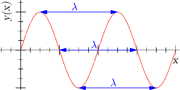
Dipole Antennas made for a frequency should measure 1/2 of a Wavelength (typically seen as λ/2).
This length is where the antenna needs to be resonant (“tuned”) on the frequency you want. Best practice is to transmit on the most resonant antenna available. If you use an antenna that is not resonant, then it won’t transmit as well and a portion of that radio energy turns to heat.
We can calculate this length using the formula:
Halfwave length (in feet) = 468 / frequency (in megahertz)
There are other considerations (wire material, wire gauge, coating, etc.) but this is a close estimate and good enough for a field expedient dipole antenna.
Knowing this halfwave length, we can either make the dipole legs (λ/4) or we can create a long wire antenna on any multiple of that halfwave.
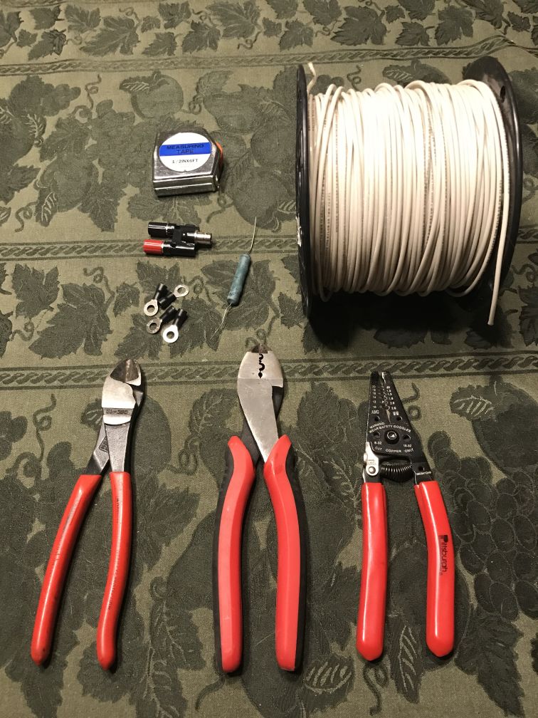
Supplies (see the Long Wire Directional Antenna Kit)
- 1 Split post BNC adapter (AKA “Cobra Head”)
- One 10-watt, 450 to 600-ohm resistor (alternatively a dead AA battery)
- Four ring terminals that fit on the BNC adapter posts. A bit larger is ok.
- A length of wire (20’+). Can be 20 AWG primary wire, 14-gauge THHN, or even lamp cord.
- 3-4 Insulators (e.g. zip ties, bootlaces, electric fence insulators, cut PVC pipe, etc.)
- A length of 550 or other cordage
- Two tent stakes or other expedient means for securing the two ends to the ground (for the Half-Rhombic version)
Tools
- Measuring Tape
- Wire Snips
- Wire Strippers
- Wire Crimpers
Assembly
- Determine the frequency you want. In this example we will use MURS 3 (151.940 MHz).
- Find the halfwave length (in feet) which equals (468/ frequency (MHz))
- Our equation is: 468 / 151.940 MHz = 3.08 feet (round to 3 feet 1 inch)
- Multiply this length by 2-4 times.
- Two halfwave lengths = 3′ 1″ x 2 = 6′ 2″
- Three halfwave lengths = 3′ 1″ x 3 = 9′ 3″
- Four halfwave lengths = 3′ 1″ x 4 = 12′ 4″
- You will need to find trees or make a support structure that is lined up with the direction you want to transmit.
- Decide which antenna you are using.
- You will need two supports for the Hasty and Rectangle variations.
- You only need one support for the Half-Rhombic but will need two anchors.
- Decide how many halfwave lengths you need to create the antenna in the space you have.
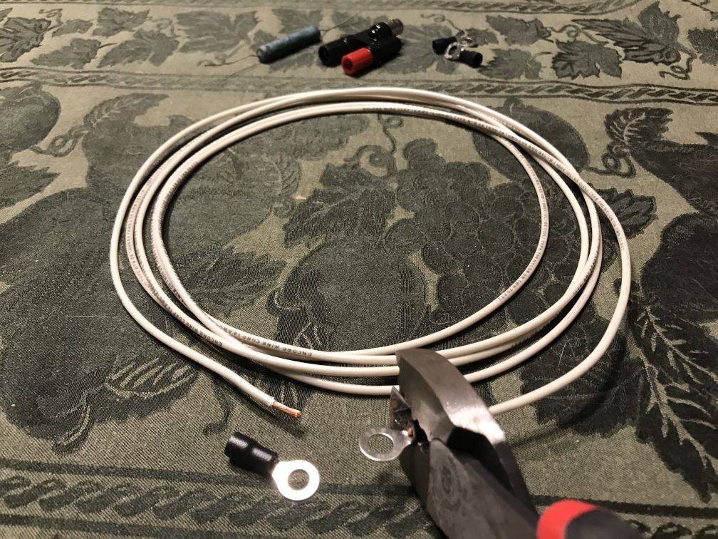
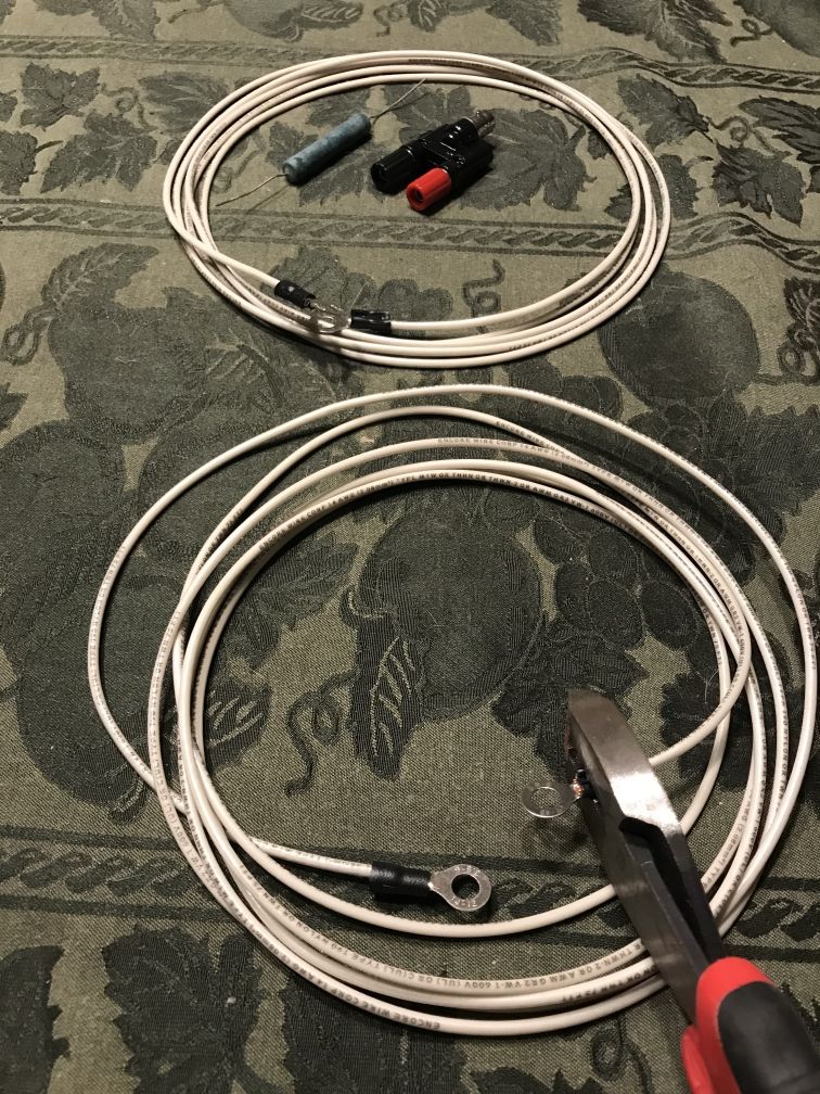
- Cut your radiator wire to the length you need. Close to measurement is good enough.
- Strip a ½ inch off each end of both wires. Crimp on ring terminals on each of these ends.
- Attach your radiator leg to the Red/Hot-side of the Cobra Head.
If you are creating the Half-Rhombic version:
- Find the middle of the radiator leg and tie it to the support structure.
- Spread the two ends of the radiator. The ring-terminal end towards your transmission direction and the Cobra-Head away from your transmission direction.
- The inverted V shape should have an angle around 110 degrees with the ends laying on the ground. You may want to adjust your middle support up or down.
- Secure the two ends to the ground with your anchors. Keep wire slightly taut.
- Stretch out your wire roll between these points and cut it to length.
- Strip a ½ inch off each and crimp on ring-terminals on each end of your ground wire.
- Attach your ground wire ring-terminal to the Ground/Black-side of the Cobra Head.
- On the other end of the ground wire, lightly loop one resistor lead through the ring-terminal.
- Lightly loop and twist the other lead of your resistor through the radiator wire ring-terminal.
- Your ground wire should be slightly taut, but there is no harm in letting it drape on the ground.
If you are creating the Hasty version:
- Attach the radiator wire to both supports loosely with cable ties. Let the ends drape over the ground by a few inches.
- The end with the Cobra-head should point away from the direction you want to transmit.
- Stretch out a ground wire between the two draping ends, add 2-6”, and cut it to length.
- Strip a ½ inch off and crimp on ring-terminals to each end of your ground wire.
- Attach one ground leg ring-terminal to the Black/Ground-side of the Cobra Head.
- On the other end of the ground wire, lightly loop one resistor leads through the ring-terminal.
- Lightly loop the other lead of your resistor through the radiator wire ring-terminal.
- Your ground wire should be laying on, or close to the ground.
If you are creating the Rectangle version:
- Create your ground leg so it matches your radiator leg length.
- Attach your ground leg to the Black/Cold-side of the Cobra Head.
- On the opposite end, connect each end of the resistor and loop it into the ring-terminals, creating a bit loop of wire.
- Attach the radiator wire to both supports loosely with cable ties and cordage. Let it drape. The end with the resistor is the direction you want to transmit.
- Attach the ground wire to both supports loosely with cable ties and cordage.
- If the antenna loop is touching the ground, then go ahead and raise it.
- You are looking for the antenna loop to be rectangular shaped, slightly taut, with rounded corners (bending these corners square is not recommended). The Cobra Head is in the middle of the back end of the antenna, the resistor should be in the middle of the front end.
Gallery


Half-Rhombic – example 1 Half-Rhombic – example 2 Half-Rhombic – resister view 1 Half-Rhombic – resister view 2 Hasty 1 – example 
Hasty 1 – Cobra-Head view Hasty 1 – radiator attachment Hasty 1 – resistor view Hasty 2 – with Cobra-Head incorrect (reversed) Rectangle – view of the resistor side


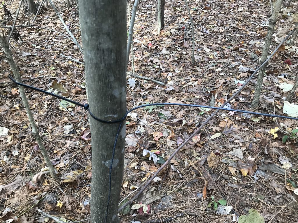


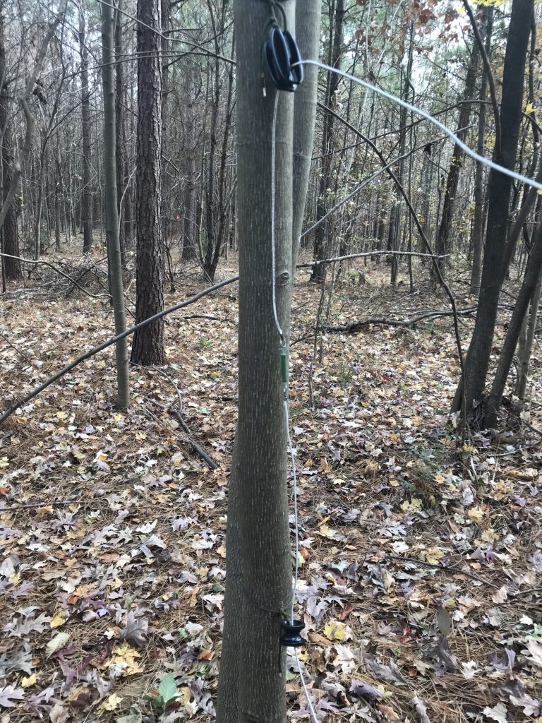
We had a oscilloscope attached to the receiving antenna. All of these antennas had strong signal output. The Cobra-Head in the Hasty 2 picture was reversed before we transmitted.
Application
When you are in the field, you should set up a Transmission Site away from your Observation Point or Hide. When it’s time to send your reports (a Communications Window), then move to the Transmission Site, quickly send your reports, then move away in a planned semi-random direction. When you know that you’ve not been observed or tracked, then move back to your Hide. In this case, since we are trying to mask our signal using a directional antenna, we can also place the antenna below the military crest of a hill to further obscure any signal. This antenna should be on the side of the hill towards your Base and away from your Opposing Force.
References/Sources
- https://brushbeater.wordpress.com/2015/10/15/the-jungle-antenna
- https://brushbeater.wordpress.com/2018/06/22/an-improvised-directional-wire-antenna/
- https://www.n6cc.com/antenna-system-ideas
- Military antenna diagram and other useful information from FM23-10 Chapter 7
- Other images from Wikipedia
Good morning and good job!
Just a question on point 6:
“Decide how many halfwave lengths you need to create the antenna in the space you have”
Should I count also the two drapes?
Thank you
Yes, do count the two drapes. When I make these it takes 2, 3, or 4 halfwaves depending on the shape of the antenna. Recently I’ve just been using 1-2 armlengths of wire and not even measuring. It seems to be good enough.